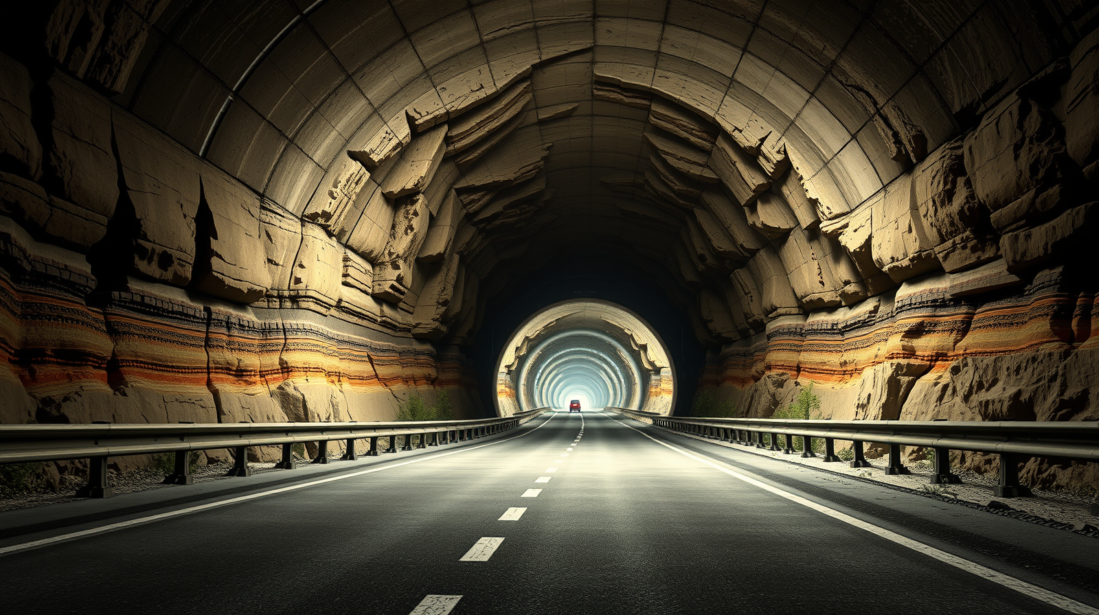
The physical constraints of constructing a permanent subterranean transit link beneath a deep oceanic fjord scale non-linearly with depth. In western Norway, the Rogfast project—a $26.7$-kilometer twin-bore subsea highway crossing the Boknafjord—is designed to reach a maximum depth of $392$ meters below sea level. At this depth, the overlying column of water and saturated rock exerts a continuous hydrostatic pressure exceeding $39$ bar ($3.9\text{ MPa}$) at the tunnel crown. This extreme pressure profile, coupled with active tectonic fault zones and highly variable lithology, invalidates conventional tunnel-boring machine (TBM) strategies. Instead, the project relies on cyclic drill-and-blast methods governed by the Norwegian Tunnelling Method (NTM) to manage structural stability and high-volume water ingress.
The primary barrier to deep subsea tunneling is not the hardness of the rock, but the hydraulic conductivity of fractured geological formations under high pressure. When a tunnel is excavated through bedrock beneath a body of water, it acts as a massive low-pressure sink. Any open fractures, joints, or fault lines intersect this sink, creating high-velocity conduits for seawater. The engineering challenge of Rogfast is a direct function of fluid mechanics, structural geology, and material science.
The Geological Matrix: Lithological Heterogeneity and Fault Planes
The route beneath the Boknafjord does not traverse a uniform geological body. The excavation profile intersects three distinct lithological domains shaped by Caledonian mountain-building events:
- Granitic Gneiss: Located primarily in the northern sections, this rock features high compressive strength but is susceptible to brittle fracturing, creating defined, high-transmissivity joint networks.
- Phyllite and Graphite-Rich Black Shales: Dominant near the southern approach and the Kvitsøy island spur. These metamorphic rocks exhibit low shear strength, high anisotropy, and rapid degradation (swelling and slaking) when exposed to air and water.
- Active Tectonic Fault Zones: These regions represent highly crushed, chaotic gouge material with virtually zero cohesion, behaving as pressurized fluid-conforming soils rather than solid rock.
[Sea Level (0m)]
~~~~~~~~~~~~~~~~~~~~~~~~~~~~~~~~~~~~~~~~~~~~~~~~~~~~~~~~~~~~~~~~~~~~~~~~~~~~~
       \                                                               /
        \                          Boknafjord                         /
         \___________________________________________________________/  [Fjord Bed]
                 |
                 |<--- ~50m Minimum Rock Cover --->|
                 |                                 |
        _________v_________________________________v_________
       /                                                     \  [-392m Maximum Depth]
      [  Twin-Bore Tunnel (Under 39 Bar Hydrostatic Pressure)  ]
       \_____________________________________________________/
                 |                                 |
                 +--- Gneiss (High Strength)       +--- Phyllite & Shales (Low Shear)
                      Fractured; water conduits         Unstable; swelling risk
This variation in rock mass quality requires continuous adaptation of the excavation face. While hard gneiss allows for longer blast rounds and minimal immediate support, the weak phyllite and fault zones demand immediate, high-density rock bolting and fiber-reinforced shotcrete to prevent immediate crown collapse.
The Fluid Dynamics of Seawater Ingress
The rate of water inflow into an underground opening is governed by Darcy's Law, which states that flow rate ($Q$) is directly proportional to the hydraulic gradient ($i$) and the hydraulic conductivity ($K$) of the medium:
$$Q = -K \cdot A \cdot i$$
At $392$ meters below sea level, the hydraulic gradient is exceptionally steep. Uncontrolled ingress through a single open joint can quickly exceed thousands of liters per minute, washing out grout, destabilizing weak rock formations, and flooding the active workspace. During excavation, inflow rates of up to $6,000$ liters per minute have been encountered at pressures up to $33$ bar.
To counteract this, the Rogfast project employs an aggressive, high-pressure pre-grouting regime. Before any blasting occurs, a series of probe holes are drilled systematically ahead of the tunnel face to map the geological conditions and measure water inflow. If water flow exceeds a strict threshold, pre-grouting is initiated.
               PRE-GROUTING SHIELD DEVELOPMENT

       Unexcavated Rock               Active Tunnel Bore
    =======================\       /======================
                            \     /
     Fractured Bedrock       \   /      Drilled Grout Holes
     (Water-Bearing)          \ /       (100 Bar Injection)
    -----------------------\   *   /----------------------
                            \ / \ /
                             X   X <--- Micro-Cement Grout
                            / \ / \      Umbrella (Pre-Sealed)
    -----------------------/   *   \----------------------
                            /     \
                            /     \     Direction of Progress ===>
    =======================/       \======================
Using computer-controlled injection rigs, a micro-cement grout mixture is forced into the pre-drilled holes at pressures reaching up to $100$ bar. This pressure, which is more than double the ambient hydrostatic pressure, forces the grout deep into the micro-fractures of the rock mass. The grout cures to form an impermeable, consolidated "umbrella" or cone around the projected tunnel path. Only after the grout has cured and probe drills confirm the water flow has dropped to acceptable levels does the blast-and-excavate cycle proceed.
Structural Stabilization: The Norwegian Tunnelling Method
Using a TBM under these specific conditions carries an unacceptably high risk of the machine becoming trapped. Squeezing ground in phyllite zones can clamp the cutterhead, while sudden, high-pressure water inflows can drown the machine's electrical systems. Rogfast therefore utilizes the Norwegian Tunnelling Method (NTM), which relies on the inherent rock mass strength of the surrounding ground to support itself, supplemented by active, flexible reinforcement.
Each cycle of the NTM consists of five sequential phases:
- Probe Drilling and Pre-Grouting: Mapping and sealing the rock mass ahead of the face.
- Drilling and Blasting: Precision drilling of blast holes, loading with emulsion explosives, and detonating to advance the face by $3$ to $5$ meters.
- Mucking and Scaling: Removing the blasted rock (muck) and scaling loose fragments from the roof and walls of the newly exposed cavity.
- Immediate Rock Support: Spraying a layer of wet-mix, steel-fiber-reinforced shotcrete (typically $100$ to $200\text{ mm}$ thick) to prevent early rock deformation, followed by the installation of systematic, tensioned radial rock bolts.
- Final Waterproofing: Installing a drain-and-membrane system covered by structural concrete lining panels to divert residual seepage into the tunnel's drainage channels.
The critical engineering trade-off of this method is speed versus safety. While a TBM can theoreticallyEngineering Under Pressure The Mechanical and Hydrological Realities of the Rogfast Subsea Megaproject
technology, news
Norway’s E39 Rogfast project, anchored by the Boknafjord Tunnel, represents a radical departure from conventional subsea engineering. Constructing a twin-tube highway tunnel spanning 27 kilometers at a maximum depth of 392 meters below sea level requires overcoming a compounding set of geological and hydrostatic pressures. At these depths, subsea tunneling ceases to be a straightforward exercise in excavation and becomes a complex battle against rock mechanics, high-pressure water ingress, and structural fatigue. The project cannot be understood through the lens of mere scale; it must be analyzed via the specific engineering mechanisms required to stabilize fractured rock under immense hydrostatic heads.
The structural viability of the Rogfast project hinges on managing three core variables: hydrostatic pressure gradients, tectonic fault zone mechanics, and the economic trade-offs of deep-sea logistics.
The Hydrostatic Pressure Dilemma and Ingress Mechanics
The primary constraint of the Boknafjord Tunnel is not the distance, but the depth. At 392 meters below sea level, the ambient hydrostatic pressure approaches 4 megapascals (MPa), or roughly 40 atmospheres. This extreme pressure fundamentally alters how water behaves when it encounters fractured rock.
In standard terrestrial tunneling, water inflow is governed by gravity and local water tables. In a subsea environment at these depths, the ocean acts as an infinite reservoir. The water pressure forces inflows through micro-fractures with immense velocity, leading to a set of distinct operational hazards:
- Erosion of Joint Fillings: High-pressure water washes out the soft mineral fillings within rock joints, destabilizing blocks that would otherwise remain interlocked.
- Grout Washout: Standard concrete or grout mixtures injected into the rock face to seal leaks can be washed away before they cure, rendering conventional sealing methods useless.
- Corrosive Degradation: Marine water introduces high concentrations of chlorides and sulfates, accelerating the chemical degradation of structural concrete liners and steel rock bolts.
To counter a 4 MPa pressure head, engineers utilize systematic pre-grouting. Instead of managing water after excavation, the rock mass ahead of the tunnel face must be transformed into an impermeable zone. This is achieved by drilling a umbrella-like pattern of injection holes up to 50 meters ahead of the blasting face.
Micro-cement or industrial chemical grouts are injected at pressures scaling up to 10 MPa—more than double the ambient water pressure—to force the grout into the tightest rock fractures against the outward push of the sea. The objective is to create a consolidated "grout umbrella" around the intended excavation path, shifting the water pressure away from the tunnel wall and deeper into the stable rock mass.
Navigating Weakness Zones and Fault Mechanics
The path beneath the Boknafjord intersects major tectonic fault zones where the rock quality degrades from competent gneiss and granite to highly fractured phillite and altered faults. These regions, termed "weakness zones," present two distinct structural failure modes.
Structural Failure Modes in Deep Subsea Rock
[High Hydrostatic Pressure (4 MPa)] ---> [Fractured Weakness Zone]
                                                |
        +---------------------------------------+---------------------------------------+
        |                                                                               |
        v                                                                               v
[Mode 1: Wedge Failure]                                                 [Mode 2: Rock Bursting / Squeezing]
- Water lubricates joints                                                - High lithostatic stress overrides strength
- Gravity + pressure drops blocks                                        - Violent fracturing or slow deformation
- Mitigation: Spiling & heavy shotcrete                                 - Mitigation: Yielding supports & anchors
In highly fractured zones, the rock loses its self-supporting capacity. The combination of high water pressure lubricating the joints and the removal of supporting rock during blasting causes immediate block fallouts.
Conversely, where the rock is intact but under massive lithostatic (overburden) stress from the hundreds of meters of rock and water above, the tunnel walls can experience rock bursting—a violent, spontaneous fracturing of the rock face as it decompresses into the newly created void. In softer rock phases like phyllite, this stress manifests as "squeezing," where the rock slowly deforms and closes in on the tunnel diameter over time.
To stabilize these zones without triggering catastrophic collapses, the excavation sequence shifts from long blast rounds to short, incremental advancements. Ahead of each blast, heavy steel pipes called spiles are driven forward into the roof of the weakness zone to form a protective canopy.
Immediately following excavation, robotically applied fiber-reinforced shotcrete is sprayed onto the exposed rock, coupled with the installation of systematic, tensioned rock bolts anchored deep into the stable rock zone. In the most severe fault zones, temporary concrete invert arches are cast at the bottom of the tunnel to close the structural ring, preventing the floor from heaving upward under the intense vertical loads.
The Logistics of Dual-Tube Safety Systems
The length of the Boknafjord Tunnel demands a strict risk-mitigation framework for operational safety, particularly regarding fire dynamics and evacuation logistics in a confined subsea environment. A single-tube design with two-way traffic represents an unacceptable risk profile; a single vehicular accident or fire could isolate hundreds of users deep below the ocean floor.
The Rogfast solution utilizes a strict twin-tube architecture. Each tube carries one-way traffic, eliminating the risk of head-on collisions and significantly simplifying ventilation design. The two tubes are interconnected by cross-passages spaced every 250 meters.
Cross-Passage Evacuation Dynamics
The cross-passages function as pressurized safe refuges. In the event of a catastrophic fire in Tube A, the ventilation system automatically adjusts to create a pressure differential:
- Tube A (Incident Tube): Longitudinal ventilation fans accelerate airflow in the direction of traffic to push smoke and toxic gases away from stopped vehicles behind the fire zone.
- Cross-Passages: Massive, fire-insulated doors lead into the cross-passages, which are kept under positive air pressure relative to both traffic tubes.
- Tube B (Non-Incident Tube): The positive pressure in the cross-passages prevents smoke from infiltrating Tube B, allowing evacuees to safely walk from the incident zone into the clear environment of the secondary tunnel, where emergency vehicles can extract them.
This dual-tube configuration also serves a critical maintenance function. Subsea tunnels suffer continuous wear from salt spray, moisture, and heavy freight traffic. The twin-tube design allows operators to close one tube completely during low-traffic night windows for structural inspections, drainage clearing, and grout maintenance, diverting all traffic to the remaining tube under strict automated signaling controls.
Strategic Operational Directives for Subsea Construction
Managing a project of this magnitude requires a departure from standard construction management frameworks. The high variability of subsea geology means that fixed-price, rigid engineering contracts inevitably lead to litigation or project abandonment due to unforeseen ground conditions.
Projects executed under these conditions must deploy the Observational Method, a structured engineering framework where the structural design is continuously updated based on real-time monitoring during construction. Every drilling round must be utilized as an exploratory probe. Measurement-While-Drilling (MWD) parameters—such as drilling speed, torque, and flush-water color—must be algorithmically analyzed to map the rock stiffness and water content ahead of the face before the next blast pattern is chosen.
Furthermore, long-term asset management must account for continuous, non-zero water ingress. It is economically unfeasible to achieve a 100% dry tunnel over 27 kilometers at 400 meters depth. The strategy must shift from absolute prevention to controlled drainage and aggressive lifecycle asset protection.
Pumping stations must be designed with triple redundancy, capable of handling not just predicted seepage, but sudden inflows from localized grout failures. Structural concrete linings must utilize high-volume fly ash or slag blends to resist marine chemical attack, and all reinforcement steel within the splash zone must be heavily galvanized or composed of stainless steel alloys to guarantee the intended 120-year design life without catastrophic structural degradation.